( ESNUG 522 Item 2 ) -------------------------------------------- [04/18/13]

From: [ Jim Hogan of Vista Ventures LLC ]
Subject: The science of SW simulators, acceleration, prototyping, emulation

Hi, John,

Functional verification is primarily comprised of:

         - software simulation,
         - simulation acceleration,
         - FPGA prototyping, and
         - emulation.

Let's look at each of them briefly, and then compare some of the elements
that relate to the speed ranges of each approach.

         ----    ----    ----    ----    ----    ----   ----

SOFTWARE SIMULATORS

A simulator is a software program that simulates an abstract model of a
particular system by taking an input representation of the product or
circuit, and processing the hardware description language and compiling it.

A system model typically includes processor cores, peripheral devices,
memories, interconnection buses, hardware accelerators and I/O interfaces.

Simulation is the basis of all functional verification.  It spans the full
range of detail from transistor-level simulation like SPICE to Transaction
Level Modeling (TLM) using C/SystemC.  Simulation should be used wherever
it's up to the task -- it's easiest to use and the most general purpose.

But SW simulation hits a speed wall as the size and detail of the circuit
description increases.  Moore's Law continues to give us more transistors
per chip, but transistor speed is flattening out.  So while computers are
shipping with increasing numbers of microprocessor cores, the operating
frequencies are stuck in the 2 - 3 GHz range.  Since SW simulators (which
run on these computers) don't effectively utilize more than a handful of
PC cores, performance degrades significantly for large circuits.  It would
take decades just to boot an operating system running on an SoC being
simulated in a logic SW simulator.

Simulation acceleration, emulation, and FPGA prototyping are all solutions
to get around show-stopping slow PC simulation speeds for large designs.
They all attempt to parallelize simulation onto larger numbers of processing
units.  This ranges from two orders of magnitude (e.g. hundreds of GPU
processing elements) to nine orders of magnitude (billions of FPGA gates).

         ----    ----    ----    ----    ----    ----   ----

SIMULATION ACCERLERATION

Simulation acceleration implements a hardware description language, such
as Verilog or VHDL, according to a verification specification.  The results
are the same as the simulation, but faster.

    - Often simulation accelerators will use hardware such as GPUs
      (i.e. NVidia Kepler) or FPGAs with embedded processors.

    - Simulation acceleration involves mapping the synthesizable portion
      of the design into a hardware platform specifically designed to
      increase performance by evaluating the HDL constructs in parallel.
      The remaining portions of the simulation are not mapped into
      hardware, but run in a software simulator on a PC/workstation.

    - The software simulator works in conjunction with the hardware
      platform to exchange simulation data.  Acceleration removes most
      of the simulation events from the slow PC software simulator and
      runs them in parallel on other HW to increase performance.

The final acceleration performance is determined by:

    1) Percentage of the simulation that is left running in software;
    2) Number of I/O signals communicating between the PC/workstation
       and the hardware engine;
    3) Communication channel latency and bandwidth; and
    4) The amount of visibility enabled for the hardware being
       accelerated.

         ----    ----    ----    ----    ----    ----   ----

EMULATORS

An emulator maps an entire design into gates or Boolean macros that are
then executed on the emulator's implementation fabric (parallel Boolean
processors or FPGA gates) such that the emulated behavior exactly matches
the cycle-by-cycle behavior of the actual system.

    - Processor-based emulator.  The design under test is mapped to
      special purpose Boolean processors.

    - FPGA-based emulator.  The design under test is mapped to FPGA
      gates as processing elements.

Elsewhere in this report, I go into more detail on emulation including:
Emulation drivers; Metrics to evaluate emulation; and a top-level comparison
chart of commercial emulation systems against those metrics.

         ----    ----    ----    ----    ----    ----   ----

FPGA PROTOTYPING

An FPGA prototype is the implementation of the SoC or IC design on a FGPA.
The protype environment is real, with real input and output streams.  Thus
the FPGA prototyping platform can provide full verification for hardware,
firmware, and application software design functionality.

Some problems associated with FPGA prototyping are:

    - Debug Confusion: Because you mapped your design into an FPGA, you
      can expect to spend some extra time debugging it, to identify
      problems that are relevant ONLY to your prototype, but that are
      not necessarily bugs inside your actual design.

    - Partitioning: Your design must be partitioned across multiple
      FPGAs.  Further, sometimes repartitioning may be necessary when
      design changes are made.  Partitioning challenges can also apply
      to emulation, so I discuss them in the emulation metrics section.

    - Timing (Impedance) Mismatches: If your FPGA prototype connects to
      real world interfaces, such as Ethernet or PCIe, then you have to
      ensure that it is capable of supporting the interface.  That is,
      mismatched timing can sometimes be a problem.  This can involve
      "speed bridging" to an FPGA.

If your design can fit into a few FPGAs, and you have adequate support, then
FPGA prototyping can be very effective -- especially when real-time
performance is vital.

         ----    ----    ----    ----    ----    ----   ----

A BASIC COMPARISION

Below I characterize the various types of hardware-assisted verification
approaches:
|
approach
|
Computational Element
|
Granularity
(# of comp elements)
|
Speed per comp element
|
Cycles per Sec (100 M gates)
|
Vendors
|
|
SW Simulation
|
X86 cores
|
under 16
|
3 GHz
|
under 1
|
Cadence Incisive/NC-Sim, Synopsys VCS, Mentor Questa
|
|
Simulation acceleration
|
GPU processing elements
|
100's
|
1 GHz
|
10 to 1,000
|
Rocketick
|
|
Processor-based emulation
|
custom processors
|
1000's
|
under 1 GHz
|
100 K to 2 M
|
Cadence Palladium
|
|
FPGA-based emulation
|
FPGA gates
|
millions
|
1 MHz - 100 MHz
|
500 K - 2 M
|
Mentor Veloce, Synopsys EVE-Zebu, Bluespec, Aldec, Cadence RPP, HyperSilicon
|
|
FPGA prototyping
|
FPGA gates
|
millions
|
1 MHz - 100 MHz
|
500 K - 20 M
|
Synopsys HAPS, internal
|
Notice that any given approach's processing elements speed is inversely
related to the approach's ultimate performance in cycles/sec. This is
basically a reflection that for functional verification, concurrency (more
computing elements) trumps clock speed (speed-per-comp element).
I put in a list of the commercially announced vendors that I am aware of.
The graphic below roughly shows how each of these basic approaches compare
relative to simulation design frequency and design size.
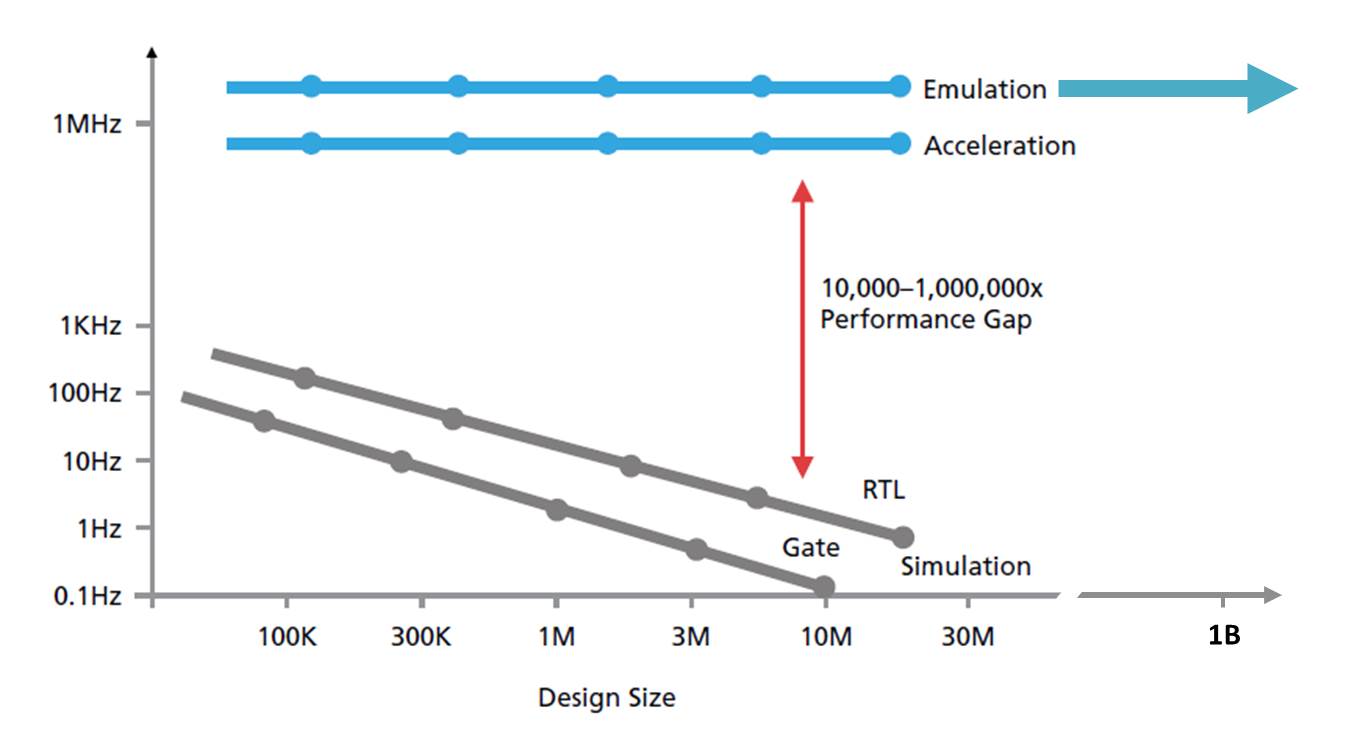 Notice emulation's 1,000X to 1,000,000X faster run time over SW simulation
as your design size goes from 10 K gates to 20 M gates. Also notice that
emulation's capacity of 2 B gates while SW simulation and acceleration both
top out at around 20 M gates -- a 100X difference in capacity.
The rest of my analysis will expand on the emulation segment.
- Jim Hogan
Vista Ventures, LLC Los Gatos, CA
---- ---- ---- ---- ---- ---- ----
Related Articles
Jim Hogan explains the 2013 market drivers for HW emulation growth
The 14 metrics - plus their gotchas - used to select an emulator
Hogan compares Palladium, Veloce, EVE ZeBu, Aldec, Bluespec, Dini
Notice emulation's 1,000X to 1,000,000X faster run time over SW simulation
as your design size goes from 10 K gates to 20 M gates. Also notice that
emulation's capacity of 2 B gates while SW simulation and acceleration both
top out at around 20 M gates -- a 100X difference in capacity.
The rest of my analysis will expand on the emulation segment.
- Jim Hogan
Vista Ventures, LLC Los Gatos, CA
---- ---- ---- ---- ---- ---- ----
Related Articles
Jim Hogan explains the 2013 market drivers for HW emulation growth
The 14 metrics - plus their gotchas - used to select an emulator
Hogan compares Palladium, Veloce, EVE ZeBu, Aldec, Bluespec, Dini
Join
Index
Next->Item
|
|