( ESNUG 522 Item 3 ) -------------------------------------------- [04/18/13]
From: [ Jim Hogan of Vista Ventures LLC ]
Subject: The 14 metrics - plus their gotchas - used to select an emulator
Hi, John,
Here are the 14 major metrics that I feel a design team must consider when
deciding on what specific emulator to use on their project (if any):
1. Price/Gate
2. Initialization and Dedicated Support
3. Capacity
4. Primary Target Designs
5. Speed Range
6. Partitioning
7. Compile Time
8. Visibility
9. Debug
10. Virtual Platform API
11. Transactor Availability
12. Verification Language and Native Support
13. Number of Users
14. Memory Capacity
Below I explain in detail the impact and pitfalls each metric will have on
your team's emulation decision.
- Jim Hogan
Vista Ventures, LLC Los Gatos, CA
---- ---- ---- ---- ---- ---- ----
1. Price/Gate
The actual cost of an emulator typically runs from 1-5 cents-per-gate
for higher capacity emulators -- both processor-based and FPGA-based.
There is usually some recurring cost for software and maintenance.
The lower capacity FPGA-based emulators are typically priced as
separate HW and SW components. The HW consists of off-the-shelf FPGA
prototyping boards that typically cost 0.25 to 1 cent-per-gate. The
SW that provides emulation features on top of the prototyping boards
are typically priced like software simulators.
2. Initialization and Dedicated Support
When assessing an emulator's total cost of ownership, the cost of
dedicated human support is a key factor, especially as it is an
ongoing expense. The large processor-based emulators virtually
always require at least one support person, if not a team, dedicated
to emulator support. It's not due to any inherent issues with
emulators; it's just the sheer scope and magnitude of the
verification projects being tackled.
The large FPGA-based emulators' need for dedicated support is similar,
also depending on the size and complexity of the emulated designs
and the number of end users involved.
Further, the time to initialize an emulator and set up models can take
6 months or more. Transactors may need to be developed to connect
test benches to the design-under-test (DUT). They are also needed to
connect host-based virtual platforms to emulators and FPGA prototyping
systems. This is part of a growing trend to improve the accuracy and
performance of virtual platforms for performance modeling and pre-
silicon software development.
The most complex transactors - such as PCIe transactors - can take
more than a year to develop. They can be the source of functionality
and performance bugs that can delay the emulation project even longer.
And test bench re-partitioning between the host and emulator may also
be required to achieve acceptable performance.
3. Capacity
There are subtle issues around an emulator's capacity; a given capacity
can be delivered in multiple ways. First, there is the straightforward
capacity measurement in terms of total number of gates: that range for
emulators currently ranges from 2 million to 2 billion gates.
Second, there is the granularity in terms of the number of devices
(ASICs or FPGAs), boards, or boxes that are used to reach a given
capacity.
Processor-based emulators are architected to provide capability in a
seamless way, where it looks monolithic to users. With FPGA-based
emulators, if it is a vertically integrated box, it should also appear
monolithic to a user. Synopsys-EVE reaches its 1 B gate capacity
in a monolithic way by connecting multiple emulator boxes.
A vendor may hide the emulator granularity from the customer, but higher
granularity generates more communication overhead, which generally
degrades performance. This is true whether the emulator is processor-
based or FPGA-based. For instance, if you were emulating 10 M gates
and it fit on a single FPGA, it could run approximately 5X faster than
if the same 10 M gate capacity were to be divided over multiple FPGAs.
Low-to-mid FPGA-based emulators typically expose more granularity to
the end user. However, an offset to this is that these boxes tend
to take advantage of the increased capacity for newer FPGA devices
more quickly than the mid-to-high-capacity FPGA-based emulators.
FPGAs on the leading edge of Moore's Law are one of the first things
manufactured. New FPGA product cycles run 12 to 18 months. In
contrast custom chip cycles are at least 4 years, and the cost of
development, which has generally been increasing for custom ASICs,
is borne by the custom-processor-based emulation vendor.
4. Primary Target Designs
SoCs are the dominant workhorse for systems companies today. The
target design sweet spot for each emulator type is typically defined
by the capacity of the emulator as it relates to your design size.
As mentioned earlier, complexity is one of the factors driving more
mainstream designs into requiring emulation. Control complexity can
require many verification cycles. Emulation applications range from
CPUs, GPUs, application processors such as video, audio, security
and datapath, to IP blocks and subsystems.
5. Speed Range
Emulator speed is measured in cycles-per-second. Processor-based
speeds range from 100 K to 4 M cycles/sec, while FPGA-based range
from 500 K to 50 M cycles/sec, depending on the number of devices.
6. Partitioning
Partitioning is harder than sounds. Partitioning would be easy if
your design could be broken up into latency insensitive blocks that
would eliminate any strict latency requirements between partitions.
But that's hardly ever the case.
- Processor-based emulators have many processing units, so large
designs must be partitioned across these units. Processor-based
systems basically run software using many cores, and the
partitioning is more or less transparent to the user.
- FPGA-based systems are hardware-centric, based on multiple FPGAs.
Due to the FPGA boundaries you must first split the design into
reasonably sized pieces, so that each sub-system will fit on one
FPGA device. Unfortunately, you then usually end up needing more
logical connections between partitioned sections of the design
than there are physical wires between FPGAs to make those
connections! These logic connections can exceed the physical
connections by 2X to 100X.
So when you stitch your partitioned design elements together to
connect them, rather than just doing a simple logical connection,
you must multiplex signal pins over the FPGA connections. This adds
substantially to complexity, particularly if this process is not
completely automated. The entire process takes additional time and
effort that opens the possibility for errors to be injected in
partitioning or reconnecting.
A deeply partitioned design can be very difficult to debug manually
or semi-automatically. Design groups sometimes give up on the task
because they can't get it right. Certain debug features don't work
as well in partitioned systems; debugging a single FPGA is easier.
Debug concern only applies to FPGA-based; the processor-based emulators
have complete visibility across all of their processors.
Most processor-based and larger FPGA-based emulation vendors try to
automatically take care of partitioning such that the end user doesn't
have to deal with it.
- Automatic partitioning is rule-based and is assumed to be
correct-by-construction. If you have a problem with your
partitioning, it's a support call to the emulation vendor.
- The greatest partitioning risk occurs in the smaller FPGA-based
emulator group. Their (in)ability to partition should be
carefully assessed -- particularly when partitioning across more
than two FPGAs. Some of these vendors use an independent
partitioning tool from Auspy; however, partitioning is
inherently never completely push button.
Thankfully, Moore's Law has now made it possible to have 30 M gates
in just two FPGAs. This neutralizes the partitioning issue for a
substantial fraction of emulation projects. If no messy multi-part
partitioning is needed, there's no problem. A single partition
between only two devices is straightforward.
7. Compile Time
Emulator compile time is the total time to prep a job for execution on
your emulation system, including synthesis and routing. For FPGA-based
emulators, compilation time is primarily determined by the FPGA routing
tools. Further, some FPGA-based emulators are starting to provide
hierarchical routing -- which enables incremental compiles.
Another variable for compile time is whether your design partitioning
between the devices is automated or not.
- For processor-based emulators this design partitioning is
automated and quite complete, and that time is included in the
compile time. The compile runs on a single workstation.
- For FPGA-based emulators partitioning can be quite variable; your
total compile time can more than double if the partitioning is
semi-automated and requires user interaction.
Another factor for compile time is whether it's parallelizable - i.e.
whether it can be broken into independent jobs to be run on separate
workstations. For FPGA-based emulators, once your partitioning is
complete, your FPGA compilation can be sped up significantly by running
each FPGA compile on a separate workstation. That's not the case for
processor-based emulators.
8. Visibility
Visibility is the ability to see signals inside a design. You have
full visibility with SW simulation, because simulation is software and
the program state is inside the simulator; it is very flexible and you
can log any state.
For FPGA-based emulators, there's static and dynamic visibility.
Static visibility refers to signal probes that are defined at compile
time. They require FPGA resources and run fast but usually cover only
a small subset of a design's signals. If you need to change that
subset of signals, you need to recompile. Dynamic visibility refers
to signal probes that do not need to be defined at compile time.
These do not require additional FPGA resources and run much slower than
static probes, but cover a much larger subset of a design's signals.
- The signal visibility with processor-based emulators is basically
the same as simulation. That's because all signal states reside
as a software addressable register somewhere in the emulation
processor array.
- With FPGA-based emulators, to see the internal signals, you must
route them out through some type of multiplexing network to the
pins. This adds physical gate overhead whenever you take a signal
and connect to it through an I/O multiplexer to the pins of the
FPGA. The multiplexer and wires create trees of logic that add
area overhead.
Additionally, those gates and wires add a performance overhead;
every cycle requires capturing the state and eventually sending
it to a host for storage. If you try to probe every signal, your
effective design capacity can go down by a factor of 2-5. You
must navigate this carefully, or your design won't fit.
However, the signal visibility gap is narrowing between processor-based
and FPGA-based emulators based on two key factors:
- FPGA capacity improvements provide increased capacity for static
probing inside of FPGAs.
- Xilinx has a built a feature in their FPGAs which offers dynamic
probes for register states. This Xilinx feature enables better
multiplexing in the chip to access the signals without overhead.
With effort, the individual emulator vendors can all but eliminate
the area overhead, which then means less time recompiling to be
able to see a different set of signals. Some emulator vendors are
taking advantage of this.
The bottom line is that emulation vendors can be assessed with an area
and performance hit for any given number of probes, as well as whether
they offer dynamic probing.
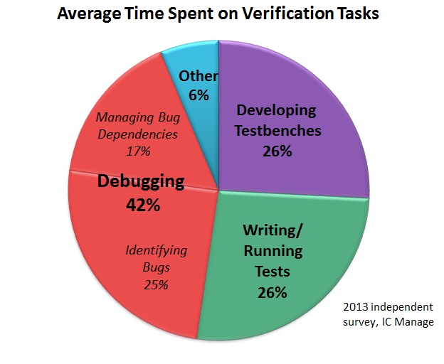
9. Debug
With the exponential rise in complexity, debug is essential - as you can
see in the chart below, teams spend 1.6x total time debugging (42%) than
they do developing testbenches (26%) and writing/running tests (26%).
 A robust debug capability is critical, and processor-based emulators
today have debug capabilities that approach that of SW simulator debug.
Fundamental emulator debug capabilities can include:
- Breakpoints. The ability to pause an emulation run based
on event triggers.
- Assertions support. It flags when assertions, or logic
statements that define the intended behavior of a design,
are violated.
- Simulation hot-swap. The ability to automatically transfer
execution to a connected simulator for more in-depth debug,
in the form of greater visibility and control.
- Software debug. It can run software debuggers on the
embedded code being executed by the processor(s).
Debug is an area undergoing significant innovation and should be
assessed beyond the simple list I show in the comparison chart.
10. Virtual Platform API
Hybrid platforms consists of emulators co-simulating with virtual
platforms, where a virtual platform simulates whole chips on a
workstation by eliminating detail from the hardware, and plugging
C-models together.
Given the prevalence of virtual platforms, it is important for the
emulator to have a standard virtual platform API, so that if an
engineer doesn't have a virtual platform C-model for a component,
they can plug the component into the emulator instead.
For example, you may have an RTL USB 3.0, but no C model. An emulator
with a virtual platform API could allow you to co-simulate with your
emulator running the USB RTL at up to 4 M cycles/sec. In contrast,
the RTL might run at only 5 K cycles/sec in a SW simulator.
11. Transactor Availability
Transactors facilitate the communication between the emulator and
other platforms with different levels of abstraction. Transactors
are critical to making emulators work in that they remove the speed
bottlenecks associated with co-emulation.
- Transactors convert transactions coming from outside the emulator
to bit-level interfaces inside the emulator and vice versa; as
emulators move to the mainstream, they need to communicate with
simulators and virtual platforms more frequently.
- Transactors also serve as interfaces when you connect inputs and
outputs to the I/O of a design (SoC) under test (DUT) in an
emulator. The transactors let you go between I/Os on the DUT to
anything communicating with it on the host simulator, C testbench
or possibly another I/O board bringing in a live connection, such
as Ethernet. Below shows an example.
A robust debug capability is critical, and processor-based emulators
today have debug capabilities that approach that of SW simulator debug.
Fundamental emulator debug capabilities can include:
- Breakpoints. The ability to pause an emulation run based
on event triggers.
- Assertions support. It flags when assertions, or logic
statements that define the intended behavior of a design,
are violated.
- Simulation hot-swap. The ability to automatically transfer
execution to a connected simulator for more in-depth debug,
in the form of greater visibility and control.
- Software debug. It can run software debuggers on the
embedded code being executed by the processor(s).
Debug is an area undergoing significant innovation and should be
assessed beyond the simple list I show in the comparison chart.
10. Virtual Platform API
Hybrid platforms consists of emulators co-simulating with virtual
platforms, where a virtual platform simulates whole chips on a
workstation by eliminating detail from the hardware, and plugging
C-models together.
Given the prevalence of virtual platforms, it is important for the
emulator to have a standard virtual platform API, so that if an
engineer doesn't have a virtual platform C-model for a component,
they can plug the component into the emulator instead.
For example, you may have an RTL USB 3.0, but no C model. An emulator
with a virtual platform API could allow you to co-simulate with your
emulator running the USB RTL at up to 4 M cycles/sec. In contrast,
the RTL might run at only 5 K cycles/sec in a SW simulator.
11. Transactor Availability
Transactors facilitate the communication between the emulator and
other platforms with different levels of abstraction. Transactors
are critical to making emulators work in that they remove the speed
bottlenecks associated with co-emulation.
- Transactors convert transactions coming from outside the emulator
to bit-level interfaces inside the emulator and vice versa; as
emulators move to the mainstream, they need to communicate with
simulators and virtual platforms more frequently.
- Transactors also serve as interfaces when you connect inputs and
outputs to the I/O of a design (SoC) under test (DUT) in an
emulator. The transactors let you go between I/Os on the DUT to
anything communicating with it on the host simulator, C testbench
or possibly another I/O board bringing in a live connection, such
as Ethernet. Below shows an example.
 Source: Mentor Graphics
- One definition of a transactor is anything that moves something
from one abstraction level to another. For example, in the
virtual platform space, transaction level modeling (TLM) is
standard, whereas in the RTL space, bit-level interfaces are the
norm.
- Hardware transactors eliminate traffic over co-emulation links to
optimize performance. They do this by translating a compound
transaction into a bit level handshake exploded in space and time
on the emulator where it's more efficiently handled. For example,
a single transaction over the co-emulation link to "move a
128-word block of memory from location A to location B" is
exploded into a sequence of 128 bit-level interface operations in
the emulator.
The overall emulator performance is very sensitive to transactor
quality. For example, an optimized transactor may have a speed
differential of 1 M cycles/sec compared with only 100 K cycles/sec
for an unoptimized transactor -- a 10X performance delta.
The individual emulator vendors provide off-the-shelf transactor libs
available for standard interfaces such as memory and high speed I/O;
these standard transactors can be used for different designs. Also,
custom transactors must often be developed for each design.
Some projects may require 10-20 transactors, of which 5-10 may be
custom, ranging from UARTs to proprietary system bus interconnects.
End-to-end performance optimization of these custom transactors is
hard -- the time can range from 1 to 12 months. Furthermore,
different transactor versions can be required to support multiple
emulation platforms.
12. Verification Language and Native Support
Regardless of transactor quality, sometimes, you must move selected
components, models or testbenches, over to a SW simulator. To do
this efficiently, ideally your emulator supports your existing
languages.
- Processor-based emulators typically have broad native support for
verification languages. This is because the emulation vendors
often also provide simulators -- an inherent advantage.
- FPGA-based emulators don't support native languages such as C++ or
SystemC; they are typically limited to synthesizable Verilog and
VHDL. The drawback is that developing synthesizable Verilog/VHDL
takes more time than writing a higher level language.
Another item that can severely limit emulator performance: when test
bench components run too slow on the host or generate too much traffic
on the link between the host and the emulator. Synthesizable test
benches running in the emulator can reduce a host emulator bottleneck
by 5X to 10X.
13. Number of Users
The bigger an SoC, generally the larger the engineering team and the
more geographically dispersed it is. Therefore, the maximum number
of users that can run an emulation at the same time on partitioned
elements of the SoC should be taken into consideration.
14. Memory Capacity
Processor-based emulators have a high memory capacity, up to 1 TB.
This memory is used more like the memory in a simulator; mapping DUT
memories is transparent and usually not an issue.
In contrast, DUT memory on FPGA-based emulators is more explicitly
mapped to hard macro memory blocks in the FPGA devices. The largest
FPGA devices have about 50 M bits per device; this capacity is usually
enough for the memory required in DUT partitions. Sometimes a DUT
memory does not map well into the FPGA device memory, in which case
the FPGA-based emulator can use special constructs to map the DUT
memory into on-board DRAM. It is important to know ahead of time
whether an FPGA-based emulator has memory configuration limitations.
---- ---- ---- ---- ---- ---- ----
Related Articles
Jim Hogan explains the 2013 market drivers for HW emulation growth
The science of SW simulators, acceleration, protyping, emulation
Hogan compares Palladium, Veloce, EVE ZeBu, Aldec, Bluespec, Dini
Source: Mentor Graphics
- One definition of a transactor is anything that moves something
from one abstraction level to another. For example, in the
virtual platform space, transaction level modeling (TLM) is
standard, whereas in the RTL space, bit-level interfaces are the
norm.
- Hardware transactors eliminate traffic over co-emulation links to
optimize performance. They do this by translating a compound
transaction into a bit level handshake exploded in space and time
on the emulator where it's more efficiently handled. For example,
a single transaction over the co-emulation link to "move a
128-word block of memory from location A to location B" is
exploded into a sequence of 128 bit-level interface operations in
the emulator.
The overall emulator performance is very sensitive to transactor
quality. For example, an optimized transactor may have a speed
differential of 1 M cycles/sec compared with only 100 K cycles/sec
for an unoptimized transactor -- a 10X performance delta.
The individual emulator vendors provide off-the-shelf transactor libs
available for standard interfaces such as memory and high speed I/O;
these standard transactors can be used for different designs. Also,
custom transactors must often be developed for each design.
Some projects may require 10-20 transactors, of which 5-10 may be
custom, ranging from UARTs to proprietary system bus interconnects.
End-to-end performance optimization of these custom transactors is
hard -- the time can range from 1 to 12 months. Furthermore,
different transactor versions can be required to support multiple
emulation platforms.
12. Verification Language and Native Support
Regardless of transactor quality, sometimes, you must move selected
components, models or testbenches, over to a SW simulator. To do
this efficiently, ideally your emulator supports your existing
languages.
- Processor-based emulators typically have broad native support for
verification languages. This is because the emulation vendors
often also provide simulators -- an inherent advantage.
- FPGA-based emulators don't support native languages such as C++ or
SystemC; they are typically limited to synthesizable Verilog and
VHDL. The drawback is that developing synthesizable Verilog/VHDL
takes more time than writing a higher level language.
Another item that can severely limit emulator performance: when test
bench components run too slow on the host or generate too much traffic
on the link between the host and the emulator. Synthesizable test
benches running in the emulator can reduce a host emulator bottleneck
by 5X to 10X.
13. Number of Users
The bigger an SoC, generally the larger the engineering team and the
more geographically dispersed it is. Therefore, the maximum number
of users that can run an emulation at the same time on partitioned
elements of the SoC should be taken into consideration.
14. Memory Capacity
Processor-based emulators have a high memory capacity, up to 1 TB.
This memory is used more like the memory in a simulator; mapping DUT
memories is transparent and usually not an issue.
In contrast, DUT memory on FPGA-based emulators is more explicitly
mapped to hard macro memory blocks in the FPGA devices. The largest
FPGA devices have about 50 M bits per device; this capacity is usually
enough for the memory required in DUT partitions. Sometimes a DUT
memory does not map well into the FPGA device memory, in which case
the FPGA-based emulator can use special constructs to map the DUT
memory into on-board DRAM. It is important to know ahead of time
whether an FPGA-based emulator has memory configuration limitations.
---- ---- ---- ---- ---- ---- ----
Related Articles
Jim Hogan explains the 2013 market drivers for HW emulation growth
The science of SW simulators, acceleration, protyping, emulation
Hogan compares Palladium, Veloce, EVE ZeBu, Aldec, Bluespec, Dini
Join
Index
Next->Item
|
|