( ESNUG 572 Item 3 ) -------------------------------------------- [05/30/17]

Subject: Jim Hogan on using Formal along with random fault verification
Systematic faults are caused by errors during the chip development process.
These can be:
- Faults introduced by human error during engineering development,
i.e. design bugs.
- Faults introduced by the software tools used for development.
E.g. a synthesis optimization that goes wrong and introduces
incorrect functionality into the design.
- A fault in the specification or requirements document. These
can be complex, and trying to make sure that you've implemented
the right thing is not a trivial task.
Crazy amounts of tracking is involved with systematic verification.
- Hogan on ISO 26262 certification and systematic verification
From: [ Jim Hogan of Vista Ventures LLC ]

Hi, John,

Now it's time to discuss the second, much more complicated aspect of testing
safety critical chips: random fault verification.  This is needed because
even if the chip was designed 100% properly, unexpected physical effects
can still occur while the chip is in operation causing it to malfunction.
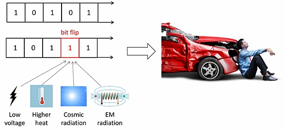
For example, the electronics in a moving car can have faults caused by the
chip getting too hot, or radiation from the sun -- or a fast spinning engine
part functioning like a big magnet that causes an electromagnetic failure.
All these effects might flip a signal value or a bit in memory to the
opposite state.
The negative consequence of random faults during operation are usually an
"on-to-off" or "off-to-on" effect.  Some examples might be:

    - The brake pedal suddenly activates during travel

    - The cruise control turns off

    - The airbag unexpectedly opens

Random fault verification requires demonstrating that a device previously
proven to be designed correctly will still operate correctly in the field
regardless of any fault that might occur.  The design is analyzed to ensure
that random faults introduced while the design is operating will not affect
the  design's performance or behavior.

Random hardware faults are typically characterized in one of three ways:

    - Permanent faults (stuck-at-0 and stuck-at-1) that are reasonably
      easy to test.

    - Transient faults such as Single Event Upset (SEU) faults that must
      be evaluated during this process.

    - Critical single-point (vs. multi-point) faults must also be tested.

        ----    ----    ----    ----    ----    ----    ----

CHIP DESIGN TRICKS TO INCREASE RELIABILITY

One first step in designing safety critical chips is to add fault handling
circuitry.  This improves reliability by inserting certain circuit elements
to increase the fault tolerance of the device.

One of the most common of these are error correcting codes or ECC.  One
well-known ECC algorithm is called a Hamming code, which encodes data bits
such that if one of the data bits changes, you can still get the original
value out.  For example, ECC codes are used with memories as follows:

    - A Hamming encoder is used on the input to the memory to encode all
      the data being written to the memory.

    - A Hamming decoder on the memory output decodes the data being read
      from memory, repairing any single bit faults.

Thus, if there is a single bit flip in memory because of a radiation or
magnetic effect, the Hamming decoder will correct this data.
Another common mechanism is to use redundancy in your design.
- In this situation, instead of only one component (e.g. a state
machine), you have multiple identical components, along with the
ability to switch out a component exhibiting a fault.
- If one component behaves incorrectly, you assume a malfunction has
occurred in that component; and use the output from another.
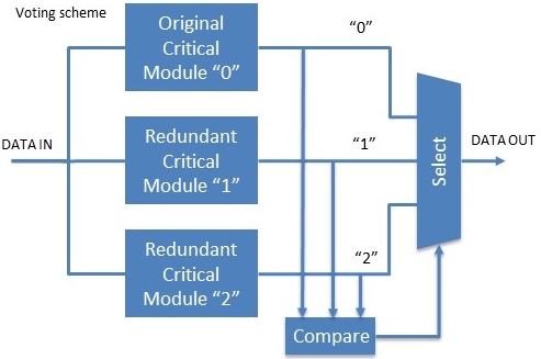
One specific form of redundancy involves three-way voting schemes.
- On airplanes, you have Triple Modular Redundancy (TMR) at the system
level; instead of one flight computer -- they have three. There's a
three-way voting scheme involved on all critical functions -- where
the odd man out is always assumed to be wrong and ignored.
- In cars, this technique is used for critical blocks within a single
chip, although it is expensive in terms of the hardware required.
There are also other methods, including lockstep and watchdog techniques.
---- ---- ---- ---- ---- ---- ----
THE RANDOM FAULT VERIFICATION PROCESS
Before, as part of random fault verification, the engineer used to mentally
go through his or her entire design to verify that none of the possible
faults in the design will impact its operation -- and explain why.
Now, there are two primary phases:
- First, do no harm. You must verify that the additional fault
handling circuitry doesn't impact the behavior of the chip when
it's running correctly.
- Recover gracefully. You must verify that for any place in the
chip where a fault could occur, that fault will either:
1) not propagate through the chip,
or
2) the fault handling circuitry will eliminate the
impact of that fault.
Verification of the Fault Handling Circuitry
Before analysis of the faults themselves is performed, the fault handling
circuitry must be verified. The fault handling circuitry must be proven
both to have no influence on the operation of the device when no fault
exists, and to handle faults appropriately when they do exist. This also
requires an extensive verification effort, and is often thought of being
part of the (earlier mentioned) Systematic Verification process.
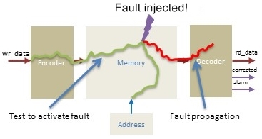
To do this, engineers need to run standard tests on the circuitry to test
operation, and then inject faults as part of the verification process to
ensure these are also handled correctly while running the device with some
appropriate stimulus or assertions.
In this diagram the acid test is to see if a fault injected into the memory
manages to propagate out of the memory to rd_data -- or does the ECC fix it
on the fly?
Also, fault injection mechanisms must be built into your RTL simulation
or formal tools so a fault may be added into a test without the design
itself being changed. These faults may be injected easily in simulation
using a Verilog "force/release" command. In formal it is more complex.
(although OneSpin has a Fault Injection app that does this.)
---- ---- ---- ---- ---- ---- ----
DANGEROUS FAULTS AND SAFE FAULTS
Diagnostic Coverage is the percentage of the faults in the design that are
either detected by the hardware safety mechanisms or proven to be safe. The
engineers must prove a high percentage of the faults won't cause a problem.
When the diagnostic coverage process begins, every single possible fault in
the design is considered a dangerous fault unless it's proven to be a safe
fault. (i.e. Every fault is "considered guilty until proven innocent".)
For an ASIL D design, 99 percent of all faults must be proven to be safe.
When a fault occurs in some part of the design, three things can happen:
- Non-propagatable fault (safe fault). The fault will get swallowed
up in the basic logic of the design and not propagate. One example:
if a fault propagates to one input of an AND gate, and the second
input is a "0", the output will still be a "0" -- and the fault
will not propagate beyond the AND gate. These faults can be
demonstrated to be safe.
- Propagatable but captured fault (safe fault). These faults ripple
through to your fault handling circuits. In these situations, you
must prove the fault handling circuit 100% eliminates the effect of
the fault.
- Propagatable fault (dangerous fault). These faults do not get
eliminated by the circuit and do not get trapped by fault handling
circuitry. Instead, they propagate through the design until they
appear at some dangerous location that can affect your chip's
operation.
---- ---- ---- ---- ---- ---- ----
USING RTL SIMULATION & FORMAL FOR RANDOM FAULT VERIFICATION
Fault simulation has been around a long time. Its original application was
to ensure that manufacturing tests would find all manufacturing faults in a
design. Fault simulation is now used in Safety Critical applications, and
operates in the following manner:
- The engineers generate a list of all the faults that can occur (the
fault population), and using the Fault Simulator injects stuck-at-0
or stuck-at-1 faults into every possible location.
- The effect of each fault is then analyzed in the fault simulator,
to check that they will not cause a problem, either because the
fault is automatically fixed by the system or it will be trapped
by the fault handling circuitry.
While fault simulation is a valuable part of random fault verification,
unfortunately it can take quite a few weeks to run all the simulations;
the fault simulation runtime is a function of the block simulation time
multiplied by the number of faults. You can optimize fault simulations
to improve performance -- for example, you can move to the next fault as
soon as the last fault is proven safe.
Using Formal in this flow can help find issues that you cannot find in
simulation, making the process more rigorous.
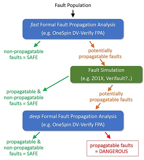
One method is to use a formal app with following methodology:
    1. Take your initial fault population and run a "fast" formal fault
       propagation analysis on it to quickly determine those faults
       that cannot propagate through the design -- and then remove these
       "safe" faults from the fault population.

    2. Run a fault simulation to further reduce the number of faults
       which may be propagatable.  This step is much faster now because
       in step #1, you've already eliminated the faults that wouls normally
       take a long time to find.

    3. Run a "deep" formal fault propagation analysis a second time to
       more deeply examine the remaining, smaller number of faults to
       understand whether they are safe or not.  Formal is exhaustive.
       It knows every state.  It will consider every possible path an
       individual fault can take through the design, providing a clear
       picture of each fault and exactly what's happening to it.

       This step removes much of the time consuming and error prone manual
       review of each individual fault to determine why it wasn't detected
       during fault simulation.

        ----    ----    ----    ----    ----    ----    ----

USING FORMAL CUTS RANDOM FAULT VERIFICATION BY 60%

The hard numbers tell the story of why you want to use Formal with your
fault simulator runs.

     Design

     Lines of RTL:  9,000              # of Equiv Faults: 24,982
       # of gates: 17,126              # of Equiv Faults: 75,358

Whenever you run just a pure fault simulation alone, you must create a
detailed testbench, which easily takes 2-3 weeks.  This testbench runs in a
few hours as a regular simulation.  But make it a fault simulation run and
it now takes 5 days.  Total time is 15 to 20 work days.

  TB write time: 3 weeks    Fault sim time: 5 days  TOTAL: 20 work days

The biggest time savings with Formal is that you only need a simple seed
testbench, which can be written in a few hours.  From this seed testbench,
the Formal tool runs off to exhaustively explore the entire state-space;
which takes 4 days.  Total time is 4.5 work days.  This is a ~60% savings.

  TB write time: 4 hours   Formal run time: 4 days  TOTAL: 4.5 work days

Beyond this ballpark 60% overall time savings, using Formal also means your
engineering staff isn't wasted doing 2 to 3 weeks of complicated testbench
writing.  Instead, the Formal tool spares them from this chore!

Next let's look at the major players in safety critical design.

    - Jim Hogan
      Vista Ventures LLC, OneSpin BoD            Los Gatos, CA

       ----    ----    ----    ----    ----    ----    ----

Related Articles

    Jim Hogan on how Safety Critical Verification is Next Big Thing
    Jim Hogan on ISO 26262 certification and systematic verification
    Jim Hogan on using Formal along with random fault verification
    Jim Hogan rates all the EDA vendors on Safety Critical IC design
Join
Index
Next->Item
|
|