( ESNUG 569 Item 2 ) -------------------------------------------- [03/31/17]

From: "Dan Joyce" <user=danj domain=correctdesigns not calm>
Subject: Dan Joyce's 29 cost-effective gate-level simulation tips (pt 2)

        ----    ----    ----    ----    ----    ----    ----

 7. Running GLS SDF with Timing Checks
    This is where GLS pays off.  SDF gatesims target four critical types of
    bugs that cannot be found with any other method.

    a) Incorrect/Incomplete Timing Constraints in Physical Design
       In synthesis, your timing constraints tell the tool how to time
       all the paths in the design, and how fast they need to be.  But
       those same constraints also are used by Static Timing Analysis
       (STA) to check that those same paths were timed correctly.  So
       it's a false check.  This is why there are massive engineering
       reviews of timing constraints.  GLS SDF finds these errors,

    b) GLS SDF and Clock Glitches
       Your chip's clocks must be extremely clean.  DFT, Backend place
       and route, gate-level fixes, power gate insertion, BIST, BISR can
       all introduce deadly glitches -- that GLS SDF can catch.

    c) CDC, Asynchronous Clocks, and GLS SDF
       Signals and buses crossing from one clock to another asynchronously
       are always critical because bugs of this type are unlikely to be
       fixed without a respin, and because simple 0-delay RTL and simple
       GLS testing will not find most of them.  Although even GLS with SDF
       is not guaranteed to find all asynchronous clock crossing issues,
       it does tend to find many that get through all other checks.

    d) Multi-Cycle Paths, Assertions, and GLS SDF
       Chip designers use multi-cycle paths to make timing more easily
       without requiring more gates or power.  Unfortunately MCPs done
       incorrectly can cause metastability or incorrect functionality
       that cannot be detected in 0-delay RTL or simple GLS.  You must use
       assertions to check for both set-up & hold multi-cycle bugs.  Doing
       GLS SDF catches MCP bugs.  WARNING: you're putting your chip at risk
       if you don't do GLS SDF and you humanly miss just one assertion on
       any of your sources or on any of your MCP destination DFFs.

    Again, notice how GLS SDF catches these four types of timing bugs above.
    Two other tips:

    - Metastability Propagates X's from Qout to Fail Tests
      Timing violations are flagged when the D-input of a DFF changes inside
      the setup or hold window around the clock edge.  Warning messages are
      printed to the log files, and the outputs of the DFF are driven to X
      for the entire clock period that the DFF could be metastable.

      Usually this X will propagate to the entire design and fail the test.
      If so, this is a real issue and must be debugged.

      If the X doesn't propagate, it still doesn't hurt to manually see if
      your design's X reduction logic is working or if you just got lucky.

    - X's are Easier to Debug
      It is quite easy to debug these failures because you don't have to
      trace back to the origin of the issue. The timing violation warning
      in the log file takes you to the source.  Even if there are too many
      warnings, X-tracing is much easier to debug in waves than trying to
      compare a passing to a failing gatesim without X's.

        ----    ----    ----    ----    ----    ----    ----

 8. You MUST Hand Review ALL the Timing Violations in your Log Files
    I know it can be mind numbing, but your engineer must sort through and
    review ALL timing violation warnings even when the tests pass before
    tapeout to find the suble timing problems that did not propagate to
    fail a test.  Create a script to filter out timing violations *before*
    reset is released; and filter out repeats of the same endpoint.

    You must pull up each endpoint in a wave showing the timing violation
    to figure why the test warned about it.  Identify the startpoint and
    endpont and review with STA to see why that endpoint should not have
    violated timing and why it actually did.

    Even when the X generated by a timing violation does not propagate to
    the rest of the design to fail a test, there may be a real problem.
    Gatesim regressions are extremely limited in coverage.  It is very
    likely that a timing violation detected by your timing checks will not
    propagate into any of your small GLS regression tests due to limited
    coverage.  This timing violation could still cause a fatal chip failure
    in silicon in a mode not tested in GLS.
(click on pic to enlarge image)
|
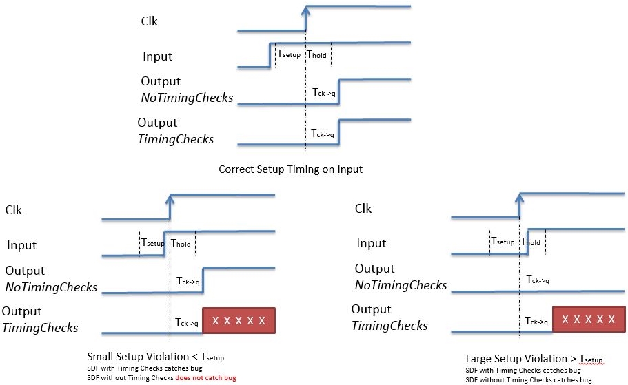
Notice how only SDF TimingChecks finds Set-up Violations
(click on pic to enlarge image)
|
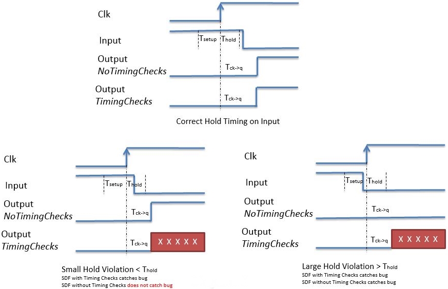
Notice how only SDF TimingChecks finds Hold Violations
These 2 diagrams above show the difference between SDF annotated timing
simulations with timing checks enabled and disabled. Both apply delays
to the signals in your design, but notice how it's only by enabling
timing checks causes the Timing Violation warning to print to the
log file and the Qout to go X.
---- ---- ---- ---- ---- ---- ----
9. One Mindful Shortcut for GLS Performance
Most chips will have block that require very long reset initialization
procedures - DDR initialization, PLL stabilization, BISR run, BIST run,
Boot Code Load, etc. These only need to be run in one GLS test. The
bulk of your tests can shortcut these reset initialization procedures
and instead do a backdoor boot load to get to the "interesting" part of
your GLS tests quicker.
---- ---- ---- ---- ---- ---- ----
10. Lint, LEC, STA, and GLS
Please! Don't do painful GLS debug with netlists that are known broken
due to earler timing or functional equivalence -- unless you just want
the practice.
- Do your Lint and LEC before 0-delay Gates
Make sure your gate-level netlist is created from an RTL design that
passes Lint checks and is LEC clean *before* running 0-delay gatesims.
Netlists are likely to have functional differences before Lint and
LEC are complete.
- Do your STA as Hold-fixed before GLS SDF
Do not run GLS with back-annotated SDF delays until your netlist is
Hold clean, otherwise the tests will not pass at any clock speed.
- Do your STA Set-up Clean before GLS SDF at Full Speed
Set-up violations are OK as long as your GLS simulations are run with
a slow enough clock. Run slow first, then full speed when netlist
is ready.
---- ---- ---- ---- ---- ---- ----
11. Using "Fake" Hold Times for GLS with SDF
It takes a lot of engineering man-hours to get SDF annotated GLS
working. And this work must be started *before* your netlist is
anywhere hear hold clean. But since, SDF Timing GLS cannot be
run without a hold clean netlist, one trick is make a script to
fake-fix hold on your netlist. This script uses your STA timing
report to list the DFFs that fail hold time. The script then adds
just enough delay at the Dinput of those DFFs to fix hold for
those paths.
- Verilog GLS SDF will Swallow Short Pulses
The tools that do Verilog SDF simulations will not propagate a
pulse through a cell that's shorter than the propagation delay
of that cell. For example, with a chip that has buffers that
have 5 nsec delay, any 4 nsec pulse will disappear in your
GLS SDF run. To balance an unfinished clock tree, sometimes
designers will just put a
assign #20 clock_666_in = clock_666__delayed_out;
thinking they just added 20 nsec to a branch of their clock tree.
What this does is makes it so a pulse less than 20 nsec will
not get propagated through! So to get around this pulse
swallowing behavior in your fake fix hold script, your added
delay must be done with multiple cascaded smallers delays instead
of one big delay. Otherwise your SDF timing misses pulses.
---- ---- ---- ---- ---- ---- ----
12. Create Slow-Clock GLS Tests First
On every project, I've found that the gate netlists only make their
timing specs very late in the design process. They are usually not
"set-up clean" until just before tapeout. But it's is necessary to
be able to run SDF simulations earlier. The workaround is to create
a knob in your tests that cause all your gatesim tests to run at
half-speed or quarter-speed clock frequencies. This gives your
project a head start on those early GLS bugs, yet you can go full
speed near the end of your project when its needed.
---- ---- ---- ---- ---- ---- ----
13. Find those Gate Bugs easier and sooner in RTL Simulation
You can use X-propagation in RTL simulation to find GLS bugs. Anything
that helps to find bugs in RTL instead of GLS is a win. GLS finds bugs
late in the design process -- where they are much more expensive to
debug and fix at that time.
A) Finding Reset Initialization Bugs in RTL Simulation
Many designs reduce size and power by using non-resetable DFFs in
their data paths. Occasionally non-resetable DFFs are accidentally
used for control logic -- and since in the real silicon these DFFs
come out of power-on into either 0 or 1 randomly, these reset-init
bugs can really be chip-killer bugs.
WARNING: RTL simulations treat X's very optimistically, while gates
treat them very pessimistically. Lately simulators have added an
X-propagation mode that causes the RTL simulation to propagate X's
more like gates, with the benefit of running at RTL speeds on much
easier to debug RTL code. Use these new X-pessimistic RTL sims
wherever you can. It'll run 6x to 24x faster than GLS.
RTL simulations gobble X's from uninitialized SRAMs as well. Since
most SRAMs do not auto-initialize, bugs of this type need to be
identified, and this can be done before GLS with x-propagation.
B) CaseX or CaseZ Bugs in RTL Simulation
Occasionally a designer needs to optimize code for speed and he uses
a casex to tell his synthesis tool to not check some of the inputs.
For this to work, the case must be non-overlapping. If there is an
overlap, it can cause multiple different synthesis results -- and
since case statements are simulated as priority encoders the RTL
simulation always picks just the first match, it's a bug. This bug
lets synthesis to pick a netlist that is never simulated until GLS.
System Verilog now has "unique case" to help avoid this if used in
the synthesizable RTL.
---- ---- ---- ---- ---- ---- ----
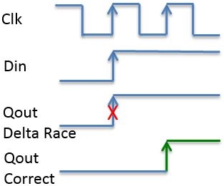
14. Delta-Delay Races aren't Usually Seen in RTL Simulation
When your Veilog simulator does not simulate a DFF correctly it's called
a delta-delay race. Instead of taking the value on the D-input *before*
the clock edge, it accidentally uses the D-input value *after* the clock
edge. It looks like a fast-path hold failure in simulation where the
Din and Qout change at the same time.
    This is a silent chip-killer if it happens in your RTL simulation;
    because your RTL functionality is different from the functionality of
    your synthesized logic.  Lint doesn't catch this.  LEC doesn't catch
    this.  The only 100% sure way to catch this is through GLS SDF runs.

    One fix is your design team could place an assertion on every DFF in
    their design, but that would be a huge maintenance issue.  A more
    palatable solution would be to have simulators add an option to
    automatically place an assertion on each DFF in your design to check
    for delta-delays dynamically.

    This is overkill for such a rare event, so it's probably OK to just wait
    for your full GLS SDF run.  Your RTL sim won't see it.

        ----    ----    ----    ----    ----    ----    ----

15. Handling X-Propagation with GLS
    The biggest complaint I hear about GLS is having to deal with its
    pessimistic propagation of X's.  Each project has to go through the
    tedious search for all X sources -- and eliminating them in a way
    that does not invalidate the GLS task.  My advice:

    - Add Pull-ups or Pull-downs on All Floating Inputs
      A surprising number of testbenches do not drive all the inputs to
      their DUT.  And a Z quickly becomes an X in GLS.

    - Initialize all Non-Resetable Elements to All-0s, All-1s, and Random
      Use an initialization mode in your simulator if available.  This
      sets all registers in your design at time 0 to all-0's, all-1's, or
      random.  Pass in a known random seed so the random pattern will be
      different for each test run -- yet repeatble for you if you need
      to repeat it.  Then run all regressions with all-0's once, all-1's
      once, and random many times for each test.

    - Treat X-gobblers as Sketchy
      Engineers like to put X-gobblers on their gate simulation models like
      RAMs, fuses, and PLLs because the RAM model authors love to drive X's
      out of their RAM.  This is OK in RTL simulation, but with GLS it
      causes everything to go X.

      Only add X-gobbler code to RAM models that you know as causing X's to
      propagate incorrectly.  Your X-gobblers should be coded to *only*
      gobble X's on gatesims.  And have plus-arg created by your simulator
      initialization command also control how the X-gobblers in these models
      convert X's to all-0s, all-1s or random.

      Note: X-gobblers in GLS do not just swallow X's like RTL sims.  They
      change the X's over to 0's, 1's, or random -- so that tests which
      correctly check for incorrect behavior will fail.  Another method
      includes depositing random values on the RAMs at time 1 psec.

    - Disable those 0-time Checkers for GLS SDF
      Some library models have checks that fail at time 0 when inputs to the
      model are X.  On SDF timing simulations the inputs to your chip don't
      make it to any modules deeper into the design at time 0 -- so those
      inputs are X until the signals propagate through the delays.  You must
      edit your models to disable those checks until the signals have time
      to propagate; typically around 50 psec into your GLS run.

    - Wave Debuggers with Good X-tracing Don't Exist
      Most GLS debugging is performed by debugging wave files.  Many tools
      exist on the market, and they all have X-tracing capabilities.  I have
      spent too much of my life tracing X's.  I'm pretty good at it, but I
      would be willing to give it up for good if someone could create a good
      X-trace feature in a wave debug tool.  CAVEAT EMPTOR: while your EDA
      salesman will claim their wave debug tool has x-trace ability, it
      doesn't.

      Wave debuggers X-tracing fails because waves are usually not dumped
      with the full hierarchy in GLS because it is too slow.

      When I am tracing an X and drop below the level that is dumped, I move
      up a level until I have waves again, then drop all the inputs to that
      module into the viewer and look for an X coming in at about the right
      time, and continue. If there is no X on an input, then I need to rerun
      with a deeper dump on that module.

      A tool that could automate this simple algorithm for X-tracing with a
      partial dump would be a huge win for GLS debug.

        ----    ----    ----    ----    ----    ----    ----

16. Tricky Delta-Delay Races in 0-delay GLS runs
    As I explained in Tip #14 (above), delta-delay races occur when your
    simulator does not simulate a DFF correctly.  Instead of taking the
    value on the D-input *before* the clock edge, it uses the value *after*
    the clock edge -- and looks like a "fast-path" hold failure in sim.

    These issues often occur in 0-delay GLS because with 0-delay, all the
    functional signals are changing at the same time as the clock edges.
    Simulators deal with this by putting the rising edge of the clock in
    the blocking portion of the zero time window (early) while the
    functional signals are restricted to the NBA (non-blocking assign, or
    late) half of the zero time window.  The way the simulator knows how
    to do this is by looking at how the signal is generated.  Clocks are
    supposed to be generated by a blocking assign (=), while functional
    logic Qout's are generated by a non-blocking assign (<=).

    Unfortunately since most clocks today are generated by a clock divider
    which uses DFF's, the clocks are generated by the Qout of a DFF.  And
    these are modeled in gates with a DFF UDP (User Defined Primitive).
    Originally UDP DFF models defaulted to blocking assigns, but a few years
    ago, the Verilog LRM changed the default to non-blocking assign.

    Either way, having the clocks and functional DFFs driven by the same DFF
    simulation model leaves a problem.  How do you tell the simulator which
    is a clock and which is not?  Simulators typically get it right most of
    the time.  Which makes me suspect the tool is identifying clocks during
    the compile of the design, and making sure those signals are always in
    the Blocking Assign region.

    But there always seem to be a few cases -- especially with hard macros,
    or weirdly coded RAM models, where 0-delay GLS fails due to delta-delay
    races.  Typically when these fails are found, they can be fixed with a
    *separate* model for DFFs driving clocks.   Another fix is to put a
    #delay on the input of the D-in, but the *separate* model approach will
    fix all DFFs on clock nets.  WISH LIST: It would be nice to have a
    compile option that would automatically place an assertion on all the
    DFFs in the RTL design that would flag any delta-delay failures
    dynamically during simulation run time. Having to do this manually
    is a maintenance headache.

        ----    ----    ----    ----    ----    ----    ----

Related Articles

    Dan Joyce's 16 bug types only found with gate-level simulation
    Dan Joyce's 29 cost-effective gate-level simulation tips (pt 1)
    Dan Joyce's 29 cost-effective gate-level simulation tips (pt 2)
    Dan Joyce's 29 cost-effective gate-level simulation tips (pt 3)
Join
Index
Next->Item
|
|