( ESNUG 569 Item 4 ) -------------------------------------------- [03/31/17]
From: "Dan Joyce" <user=danj domain=correctdesigns not calm>
Subject: Dan Joyce's 29 cost-effective gate-level simulation tips (pt 3)
---- ---- ---- ---- ---- ---- ----
17. Keep your RTL and Testbenches and Gate Netlists in Sync
The earlier Tip #2 above says to allow easy debug of failing tests,
you must have three DUT models running identically so that debugging
failing tests is easier - by comparing passing waves to failing waves.
This won't work if your RTL DUT is different from your Gate DUT.
Problem: It takes a few weeks for your Physical Designers to generate
a new Gate Netlist from RTL. Before design freeze, this is a real
problem because the RTL is changing all the time. Note that the same
issue exists with your testbench and tests - they also need to match
the Gate Netlist.
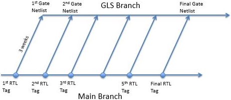
Solution: when PD delivers a netlist, they provide a tag of the
repository of when the RLT DUT was pulled for synthesis. When you
receive a new Gate Netlist, you checkout from the repository from
the main branch at the same RTL tag PD made when they pulled the RTL
for synthesis. It's a parallel branch off your GLS Repository Branch.
This is pretty standard in the GLS world.
- It's Easier to Archive each Netlist
At some point it will be necessary to checkin your GLS changes.
Usually RTL verification teams do not tolerate "`ifdef GLS"
splattered all over their testbench. If you check your GLS changes
into the Master Repository, this GLS stuff will go into the Master
Repository testbench code.
Makes an additional set of "temp `ifdefs" as well. You have to update
to the Master Repository Branch to checkin to it -- which breaks GLS
on this Netlist because it pulls in changes that don't match that now
very old Gate Netlist. These must be "temp ifdef'ed" as well to allow
the GLS tests to pass. So then two sets of "`ifdefs" are polluting
the Master Branch of the repository.
      Instead, it is possible to keep the GLS branch separate from the
      Master - see the diagram above.  Never merge back nor checkin to
      the Master.  Keep the GLS Repository Branch as a parallel branch
      that pulls from Master every new netlist to update testbench and
      chip RTL, but never merge back.  Tag the last checkin of each
      netlist as an archive.  Only after tapeout you merge back.

    - Insulate your GLS Repository from RTL Repository Churn
      Another big GLS problem is the Master Branch repository has a great
      deal of churn.  Checkins are constant, and the repository is often
      broken.  Since Gate simulations are too slow to include in the
      release regressions, the gate tests are the ones broken the most.

      And since GLS is so much more painful to debug than RTL simulations,
      it's best to insulate the GLS branch from all the changes going into
      the Master branch.  The GLS branch does that for you automatically
      since changes are pulled in from the Master only with each new gate
      netlist.

        ----    ----    ----    ----    ----    ----    ----

18. Use Probes and Forces only on Physical Block Boundaries
    During RTL synthesis the gate netlists rename most of the signals
    inside your DUT, so probing internal signals from the testbench is
    not doable.  This also impacts using "force" commands, too.

    Plan for this by having your Physical Design team have their synthesis
    scripts keep the names of the signals that you want to probe from the
    testbench.  Most PD groups do this by preserving all of the ports on
    the physical block boundaries.  Then you the test guys must follow
    the rule that all testbench interfaces must connect only to ports on
    these blocks.

        ----    ----    ----    ----    ----    ----    ----

19. All your GLS Checks and Regressions must be PASS or FAIL
    To keep things batchable, you must have *all* of your tests to be
    completely self-checking and regressionable so that they can run
    overnight on a pool of servers.

    As for as checking, there are two types of Gatesim tests.

    a) C-code, Hex, or Assembly Code GLS Tests
       These are code stimulus and checking tests are written in C and
       then compiled to assembly hex files that are checked into your
       repository.  The testbench releases reset on the DUT, and loads
       this hex file into the external RAM or ROM model in the testbench,
       or back-door loads an SRAM inside the DUT. The testbench releases
       reset on the DUT and waits for a handshake.

       The handshake is usually a location in memory that both the DUT
       and the testbench can access, or some use of IO's to communicate
       between the testbench and DUT.  The DUT boots from the hex code
       and performs the test on it's own.

       NOTE: These hex tests should bring any peripherals out of reset,
       and check that RAMs, registers, DDR, peripherals, etc. can be all
       read and written correctly through all of the interconnect in
       your chip.  This is done with a write followed by a read so the
       hex code can self-check.

       If data is correct, it goes on.  If incorrect, the test fails
       immediately by writing the handshake PASS/FAIL location that the
       test has FAILED, and the DONE handshake location that the test is
       finished.  Meanwhile the testbench verification thread has been
       polling the DONE location since releasing reset and when it is
       seen to be true, finishes the test, writing out PASS/FAIL and as
       much information as possible to the log file.

    b) GLS BFM tests
       These are Monitor checking tests that use BFMs mixed in with your
       GLS to stimulate and check correctness.  These tests are easier to
       write and debug than assembly hex code driven tests because they're
       usually leveraged from your earlier RTL regression.

       The catch is that they require Cross Module References (forces and
       probes) into your DUT -- which is very tricky with Gate Simulation.
       Your gate netlist must preserve all of the signals to be probed and
       forced in each version, or there must be a mapping file for each
       netlist that can be easily used to connect the signals to the
       testbench.

     GLS SDF timing simulations are even trickier as we later discuss in
     the next tip (Tip #20) below after this section.

     The 4 Goals of Picking Tests for GLS
     This all sounds obvious, but often the way a test checks for functional
     correctness of your DUT can make or break your GLS effort.  There are
     4 goals of picking GLS tests.  In order of priority:

       GLS Test Goal #1: No False Fails
       Your tests must check for correctness in a way that is not brittle.
       It has to be robust.  You must be able to change clock frequencies
       and skew stimulation on your GLS without causing the test to flag a
       failure incorrectly.  Chasing down these False Fails is very costly
       and can quickly make GLS not cost-effective.

       GLS Test Goal #2: No False Passes
       Obviously a False Pass could allow a bug to get into silicon.  You
       need to know that if you get a GLS PASS on a test, that test really
       did a complete enough check that you *know* the logic is working
       as required.  You have to know that PASS means it actually PASSED.

       Note: Many are surprised that I prioritize robust tests over a
       higher level of functional checking.  This is because GLS bugs are
       usually gross bugs where the symptom is large, so checking does not
       need to be fine grained.

       More important than fine grained checking, Gatesims require subtle
       stimulus especially around clocks.  These tests must be able to
       handle clock skewing and walking clocks past each other without
       False Fails.  Otherwise you will not be able to run those clock
       skews, and much of the value of GLS will be lost.

       GLS Test Goal #3: Make Test FAILS Easy To Debug
       Failing tests should be easy to debug.  This means they should not
       just hang.  And when a test fails, there should be some indication of
       time and location of the failure.  Make sure your code driven tests
       have checkpoints to show key accomplishments.  Write to a log file
       when the core is out of reset, when DDR initialization is complete,
       when clock switches finish, etc.  Monitors should show information
       in log files instead of having to rerun with dumping.

       GLS Test Goal #4: Choose Low Porting Cost Tests
       Having to translate checkers from RTL to Gates can be extremely
       expensive.  Don't port everything over willy-nilly.  Instead you
       have to figure out how many man-hours it will cost to do each
       port.  (One exception though: if your RTL tests have really
       good Ease of Debug or No False Passes features, yes port them.)

       Also, expensive translations per-test is worse.  For instance,
       having to translate from BFM over to GLS Code Driven is very
       expensive.

        ----    ----    ----    ----    ----    ----    ----

20. Tricky Verilog "clocking... endclocking", BFMs, and GLS SDF

    Roughly 10 years ago, the Verilog standard was changed to allow for
    clocking blocks.  They're used in BRM interfaces to let the BFM drive
    and probe signals and buses inside a SDF annotated gate netlist with
    Hold and Setup margin.  Makes internal BFMs in GLS SDF runs easier.
    Otherwise you'd have to create a timing ring and change signal delays
    for each new netlist - sometimes even on a signal to signal basis.

    - The GLS BFM Timing Problem
      BFMs are used to replace a complex core with a simple read/write
      interface driven by testbench tasks and sequences.  But that BFM
      only works if the timing between the clocks and the data makes
      setup and hold.  In 0-time RTL and 0-delay GLS, both data and clocks
      occur at the same time, and the "non-blocking" data signal changes
      happen after the "blocking" clock edges.  But when trying to use
      an internal BFM in a GLS with back-annotated SDF timing applied to
      the netlist nets, the point where the BFM is binded into the DUT
      to probe and force the data signals gets arbitrary timing.

      Depending on what node is chosen in the path, there is delay on
      both sides of the bind point for both the clocks and the data.

      This causes hold violations to occur in both directions.

    - DUT to Testbench and Testbench to DUT.
      Verilog clocking blocks let you capture data from the DUT to the
      Testbench at a time prior to the clock edge.  This is when all
      the bits on a bus are in sync and stable to capture and send to the
      Testbench (specified with a #SETUP_TIME before the clock edge).

      Likewise, when the Testbench is driving a bus into the DUT, a
      clocking block lets you set a #HOLD_TIME delay on all Testbench
      outputs to make sure that the DUT will capture all those data
      bits when they are on the same clock.

    WARNING: Verilog clocking blocks are a quick fix to BFM timing issues,
    but they bring unexpected problems that can be hard to clean up.

        ----    ----    ----    ----    ----    ----    ----

21. Manually Review ALL "forces" in your Testbench
    The Verilog "forces" construct is often used in verification as a
    temporary workaround.  These can be mistakenly left in your Tests
    or Testbench, thus masking real hardware bug.

    GLS mostly catches these leftover "force" issues because the GLS
    netlist usually changes the names of signals in the RTL DUT; making
    the compile fail from a messed up Cross Module References file.

    However since more netlists are now preserving internal signals and
    hierarchy, you must still go on a search & destroy mission against
    all "forces" in your later GLS runs.

    - Turn off all Forces for at least 1 Reset Initialization Test
      Be sure to do at least one full GLS full reset-initialization of
      your entire chip with no "forces" at all.

    - Roll your own Dynamically Traceable "Force" Macro
      Create a force macro that prints a message to the log file every
      time it forces a signal in the DUT.  Use this macro when you want
      to find any leftover "forces" lurking in your DUT.

        ----    ----    ----    ----    ----    ----    ----

22. Go Fast & Lean with those GLS Fails
    Runtime performance is key to debugging failing gatesim tests.  When
    you're given a new gate netlist, port your testbench to it, and run
    the gatesim regression on it in a batch mode on a server pool.

    Do this run in the fastest mode with no dumping to optimize CPUs and
    disk space.  Don't waste time with SDF runs, if you haven't yet done
    0-delay GLS runs.

    The next day there will be a boatload of failing tests.  Debugging
    usually involves rerunning the failing tests with wave dumping,
    which costs another day.  If there are monitors stitched into the
    netlist at key points, it may be possible to identify the source of
    a failure quickly without even having to rerun the failing tests and
    dump to waves.

        ----    ----    ----    ----    ----    ----    ----

23. Testing for Clock bugs with GLS SDF
    One of the most critical parts of any chip are its clocks.  Good clean
    clocks result in solid performing chips.  Bad clocks give you chip
    hangs, and intermittent behavior.  Unfortunately clock verification
    is very hard to do in our ideal 0-delay RTL simulators which are tuned
    for performance.  There are four critical types of clock bugs that you
    must hazard your way through.  FIRST, create tests and checkers for
    clock bugs and run them in RTL.  THEN, port them to 0-delay GLS, and
    then GLS with SDF back-annotated timing.

    - Clock Glitches & GLS
      Glitches are very unlikely to show up in your RTL simulations because
      they are often introduced into your chip during either the synthesis,
      or place and route stages.  For testing, target your glitch checkers
      on clocks and resets -- any anything else that's glitchy -- and then
      run 0-delay GLS, then SDF GLS.

    - GLS SDF and Max Frequency Violations
      Max frequency bugs are when two clock edges are closer together than
      the logic using that clock was timed to handle.  It results in logic
      hangs.  Place maximum frequency checkers on your clocks and then go
      straight to running GLS with SDF.  Don't bother with 0-delay here.

    - Asynchronous Clock Crossings with GLS SDF
      The highest risk part of any design today are its asynchronous clock
      crossings.  Running diabolical self-checking stress liveness GLS SDF
      tests is not guaranteed to find every problem, but a surprising
      number do get caught this way.

      Make sure the asynchronous clocks are walked past each other with
      prime number dividers or with very random generation which do not
      result in harmonics.  The more varied the clock relationships in your
      tests, and the more SDF corners you run with timing, the more likely
      the SDF GLS will find the bugs.

    - Dynamic Frequency Changes and SDF GLS
      Low power designs today require dynamically changing frequencies
      without quiescing the logic.  Create highly strenuous self-checking
      liveness tests with high frequency dynamic clock changes and run
      them on gate netlists with SDF timing.  Make sure your base clock
      frequencies walk past each other.

        ----    ----    ----    ----    ----    ----    ----

24. Reset Timing with GLS SDF
    Many large designs today have a clock zone that is so large, it is
    not possible to bring all of the DFFs out of reset on the same clock.
    This is a problem if more than one DFF will change state on the first
    clock edge out of reset.  Running reset-initialization tests on GLS
    with SDF timing can find these bugs.  But when your logic is known
    to have this problem, care must be taken in designing it to be "reset
    aware" and then for you to later verify that logic works for resets.

        ----    ----    ----    ----    ----    ----    ----

25. Using GLS for Power Estimation
    Low power designs require very precise analysis of the power before
    tapeout.  There are tools that can estimate this power, but many teams
    need a more precise measurement.  These tools require a GLS full dump
    file of the chip in a high power mode.  Create this dump using GLS
    with SDF timing to get the most realistic power measurement.

        ----    ----    ----    ----    ----    ----    ----

26. CRUCIAL: Archive each Netlist and "How To" Technique
    Often there is one engineer who knows the GLS environment and does the
    port of the new netlists each time the Physical Design team delivers
    him one.  This porting process is key to the progress of GLS since it
    is so easy to insert simulation problems during this step; and GLS
    simulation problems are so hard to debug.

    The owner of this port must carefully babysit all the changes from one
    netlist to another netlist -- especially around the IP.  The steps in
    his porting process should be well documented for each port, since his
    next netlist port will start with those exact same steps.

    Having at least two people who at least know how to perform the port
    is important.  Sometimes with GLS, like with fabs, you can "lose the
    recipe."  You can have new netlists from PD that are seriously
    broken; or testbench or simulator version changes, that causes
    everything to fall apart.  The ability to pull up a previous netlist
    that was passing makes it much easier to debug new problems with new
    netlists.  YOU MUST tag and archive each netlist with a clear HowTo of
    its porting.  This archive must include how to pull up a previous tag
    of the GLS environment for all previous netlists, how to run the
    previous netlists regressions at their most stable tag, which tests
    were passing and how long they ran, and what simulation options and
    tool versions were used.

    This is probably the most important step that is usually neglected.

        ----    ----    ----    ----    ----    ----    ----

27. Don't Start Fixing GLS Issues 3 Weeks Before Final Tapeout
    The momement you get your first RTL model, you should start creating the
    GLS environment you're going to be using on this chip.  Flush out your
    gate-level model issues with an early gate-level netlist release.

    Remember that 19 out of 20 gatesim test failures are due to simulation
    problems, not netlist bugs.

    The goal of your GLS environment is to make sure when that final netlist
    arrives 2 weeks before tapeout, you can run your regression that was
    passing on the last 17 netlists -- and have all of your GLS simulation
    issues be solved.  You should only be dealing with real bugs in this
    critical last stretch.

        ----    ----    ----    ----    ----    ----    ----

28. Figure Out Why You Didn't Catch That Chip-Killing Bug Earlier
    On paper, GLS should never find any bugs.  All of the processes we use
    today (LEC, lint, STA, formal, ABV, etc.) all make sure the gates we
    generated for silicon manufacturing actually operate as intended.
    But GLS is a very cost effective orthogonal re-check of what those other
    tools do.

    But in my experience there have always been chip-killer bugs I've found
    by GLS.  Because those bugs are found late in the design process, it is
    obvious they would not have been found *without* GLS -- and their fix
    is usually an expensive Gate Level Fix -- or recompile often delaying
    your tapeout.  This gives sudden visibility to the issue and gets
    management attention, which causes an examination of how that bug
    escaped your existing tools and verification processes.

    Use this crisis to your advantage.  Use it to improve your overall chip
    design and verification process.

        ----    ----    ----    ----    ----    ----    ----

29. CRUCIAL: Find the Right Person
    GLS pushes all the tools to their limit.  It's a constant fight against
    performance issues, weird tool problems, and library issues.  Most of
    a GLS engineer's time is spent looking for workarounds that won't
    compromise the integrity of his GLS for non-design related issues.

    You want an engineer with the confidence to make the tough calls.
    Deciding between multiple paths of progress is a constant headache,
    and requires the ability to understand the risk of alternatives;
    since some workarounds will save huge amounts of effort with little
    risk, while others can invalidate the GLS.

    When your simulation tool or wave viewer has a bug, the EDA vendors
    usually won't have a fix in time for your tapeout.  And even if they
    did it is very unlikely you will be willing to change to a newer
    version of their tool just before tapeout.  So you will be looking
    for workarounds.  Your GLS engineer has to know how to both figure
    out these workarounds and/or to "woo" others (coworkers, FAE's, his
    IT department, his managment, whoever) to get this workaround.

    Multi-day RTL & GLS simulations require the ability to work on many
    things in parallel.  Organization is key.  I often have 20+ workareas
    going at a time.  So having a way to keep track of what is going on in
    each, is the only way to context switch without losing track.  I will
    typically try many experiments at once to get around a problem because
    it will take a day to see if any worked, and trying them in serial
    would take a week.

    Usually engineers will work on GLS for one chip and never want to do it
    again.  Most likely the person was not a good fit for this type of work,
    or his environment was not up to the task, or both.

    MGMT TIP 1: if you find an engineer who's good at GLS, it's wise to
    make it worth their while to work at your company.  :)

    MGMT TIP 2: make sure to give extra disk space for the Gatesim team.
    Typically 5 - 10X what they give others.  A separate partition or
    two for the gate team would be good since they fill up disks fast.

THE DAN JOYCE PERSONAL GUARANTEE: As I said before, with the techniques
that I've outlined here, I've personally found at least 1 killer bug on each
of the 22 chips I've worked on in my career.
I'm so sure of GLS, and since DAC'17 is coming to my home of Austin in
10 weeks from now, I will persomally treat anyone to a full steak dinner
with all the trimmings at Perry's Steakhouse at 114 W 7th Street if they
religiously used these 29 GLS tips and failed to uncover a previously
unknown chip-killing bug in their design.

    - Dan Joyce
      Correct Designs, Inc.                      Austin, TX

        ----    ----    ----    ----    ----    ----    ----

|
Dan Joyce works as a verification consultant at Correct Designs in Austin, TX. When he's not listening to his wife bitterly complain about Trump, he likes to nap. "I love napping!" Non-robots can reach him at <user=danj domain=correctdesigns not calm>
|
Related Articles

    Dan Joyce's 16 bug types only found with gate-level simulation
    Dan Joyce's 29 cost-effective gate-level simulation tips (pt 1)
    Dan Joyce's 29 cost-effective gate-level simulation tips (pt 2)
    Dan Joyce's 29 cost-effective gate-level simulation tips (pt 3)
Join
Index
Next->Item
|
|